![Bruce[2].jpg (4158 bytes)](images/Bruce[2].jpg) Bruce Roberts-Goodson |
|
 Illustrated Custom Boatbuilding. We recommend that you read this hardcover book - Order now and we will pay the postage. HOME PAGE |
FIBERGLASS BOAT BUILDING NEWS Hi fellow boatbuilder, this is the start of our on-line FIBERGLASS BOAT BUILDING NEWS that is updated on a regular basis. We can only share with you a fraction of the information included in our BOAT BUILDING STUDY boat plans & Complete boat plans & PATTERN packages. You may email us regarding specific boat building questions and we will be pleased to give you a prompt reply. In the meantime ...good boat building ....from us all at Bruce Roberts. Please email me your comments on our site....criticisms as well as other comments please. There are many & varied methods of fiberglass boat building, we will try and explain each method in sufficient detail to enable you to make a decision as to which boat building method is best suited to your requirements. In general round bilge hulls such as sail boats are best built over a batten mold & power boats are usually but not always built in a female mold. We have developed a 'cheap one-off mold' fiberglass boat building system that is ideal for building larger powerboats. |
BUILDING THE
EZI-BUILD FEMALE MOULD First we will look at the female mould method. Back in the early 1960’s, we were designing fishing trawlers that could be built of fibreglass using inexpensive one-off or limited production moulds. With the current rise in the number of people interested in power boats and the acceptance of chine hulls in general, we decided to simplify and streamline our original methods to make them suitable for one-off production by amateur and professional builders. When looking at these techniques, we were developing a new range of power boat designs using the latest CAD software so that these designs did not involve difficult curves but instead were easily assembled in simple one-off moulds. These new designs all reflected the ability of the computer to produce absolutely fair, developable hull surfaces suitable for turning flat sheets of fiberglass into attractive hulls. Most of the original designs were directed towards steel or aluminium but the demand for similar fiberglass methods led us to develop computer lofted hulls with full developable surfaces and the result is the Ezi-Build technique.
MAKING THE
FRAMES “EZI-BUILD” Build the hull frames in a way that provides an outer framework to support the whole mould structure details of which should be in your plan. In designs under 32 feet [10 metres], the bottom of the support structure can be canted 45 degrees which will enable the whole structure to be tilted, side to side, for easy lamination. On larger hulls, it is advisable to hang scaffolding inside the hull structure to support planks for working from. SPLIT MOULDS
|
|
|
INSTALLING
THE BATTENS This is how your mold will look in profile. Not all battens are shown for sake of clarity, |
CHOOSING THE MOULD LINING
When all the battens are installed and you
are satisfied with the fairness of the mould, the next job is to install the
lining. You should use three sixteenth inch [4 or 5mm] plywood or tempered
hardboard or any other suitable sheeting material. If you use plywood it
will need to be coated but be sure that the coating is compatible with the
fiberglass – do a test. From this stage onward work closely with your
fibreglass materials supplier and take his advice on the correct wax and
release agent to use on the mould.
INSTALLLING THE MOULD LINING
No matter which mould lining material you
choose, it will need to be attached to the battens with a contact type
cement. Nail only where absolutely necessary as the nail heads will show
up in the finished laminate and can be difficult to fill. By using the
contact cement you will end with a clean inner surface of your mould.
Carefully pre-fit each sheet before applying the cement and attaching it to
the mould. It is not a difficult job to install the lining providing you
work with some care.
|
|
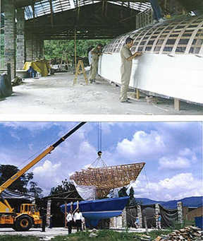
FINISHING THE MOULD Here we see the mold set up ready to receive the laminates. Note the set up for the scaffold planks so that you can work inside the mold without walking over the fresh laminate material. The boat plans have much more detail than can be included here. |
FINISHING THE MOULD
Once you have installed the mould lining, you should fill any small gaps
with mould wax. Also, radius any areas where you need to have rounded
corners. For this job, you can use body filler or any other polyester
based material that is compatible with the fibreglass laminate you will be
installing. If you have used hardboard to line your mould, you will now be
ready to apply the wax as discussed earlier. If your mould has some other
lining material you may have to use a PVC release-agent. You should talk
to your material suppliers about the most suitable system.
INSTALLING THE LAMINATE IN THE
EZI-BUILD MOULD
Even if you later intend to paint the hull the most important part of the
laminate is the gel-coat and first layer. We would recommend you use some
form of gelcoat, either pigmented or clear. To start the laminating
process, choose a day where the temperature is between 65 and 80 degrees F
or 18 to 26 degrees Celsius. Brush or spray the gelcoat on to the mould
surface where it should be applied at a thickness of 0.5mm. You can
measure the thickness of the gel-coat by using a special gauge obtainable
from your fibreglass supplier.
Ideally, you should use a clear isothalic NPG gelcoat and back it up with a layer of surface tissue and vinyl ester resin. This is important so see your resin supplier about getting the right materials if you want to be sure of increased resistance to water permeation and avoid any possibility of osmosis, at a later date. You will need two or three helpers as you start to lay up the hull and it is advisable, for temperature control, to be at the same stage of lamination each day with each successive layer. If the laminate overheats from applying too much material at one time, it may cause distortion and pre-release from the mould.
FIRST LAMINATES
The day after you have applied the gelcoat,
you should apply the first layer of light chopped-strand mat, usually Į
ounce per square foot [200 g/m 2]. This layer is very important and should
be carefully rolled out to avoid any chance of air bubbles. Air bubbles in
any layer are a nuisance but in the first layer, they could lead to
problems. Vacuum bagging is one solution to avoiding these voids –
see chapter.
Once the gelcoat and first layer of mat are in place you will have passed the most critical stage of your laminating process. Providing you follow some form of temperature control, you should go on to complete the laminate without any problems. As mentioned earlier, always finish your laminating at the same part of your hull each day. Three willing workers can lay up a fifty foot [20 metres] hull in a few days. Two layers of fibreglass per day, one mat and one roving, is a reasonable amount to install at one go without causing the laminate to overheat. New resins are being formulated all the time so you must have the latest technical data and support from your materials supplier.
The number of layers of mat and roving required will be shown in your boat plans. After the layers that cover the whole hull surfaces are completed, you will most likely be required to install extra layers in the areas of the keel and below the hull waterline. Most laminate schedules call for overlapping and or interleaving the various layers in the areas such as the chine and keel, thus building up extra strength where it is required.
Again, we remind you to trim the sheerline of your hull each day. This will usually be done as work progresses and about an hour after the final layer for the day has been installed. Once you have installed the basic laminate and any extra layers called for in your plan laminate schedule, you should add any stringers, sole shelf, deck shelf etc and any other reinforcing members called for in your boat plans.
You should then install all the ribs, stringers, bulkheads and web floors before you remove the hull from the mould. After you have completed the installing of the stringers and ribs etc and if you do not plan to use the mould again, you may prefer to remove only the mould above the chine or water line, leaving the bottom section to act as a cradle.
|
Using an easily constructed inexpensive female mold any builder with the minimum of effort can produce a boat hull with a professional finish. |
EZI-BUILD SANDWICH HULLS
If you are building an Ezi-build sandwich hull, then you will lay up the outer laminate plus any extra layers in the critical areas, before you install the core material which may be PVC foam or end grain balsa. In either case, the best method to install the core is to use Vacuum bagging techniques that are described elsewhere in this book although the core can be installed manually. If you intend building a sandwich hull, please read the chapters on one off building, where you may pick up a few ideas on the handling of core materials.
PANEL CONSTRUCTION
The panel method of building a one off fiberglass boat is a variation on the Ezi-build technique. The method is ideally suited to building chine hulls including CATAMARAN and any power boat or single or multi-chine sailboat hull. The main advantage of using this technique is that a full mould is not required. You will retain the advantage that a minimum of finishing is required for the outer surface of your hull. Very little filling and sanding will be needed to achieve an excellent professional standard of finish.
For panel construction, the system of building the female frames and setting them up on a set of bedlogs, is similar to the methods used when building an Ezi-build mould. Only a few battens are required to hold the frames square and vertical. The technique of setting up the basic framework to hold the fibreglass panels is similar to the first stages of building the Ezi-build mould. The fewer battens required and the absence of a mould lining material, are the main differences between the Ezi-build and the Panel methods.
Additional bracing is used on the outside of the frame assembly and once the frames and the few battens are installed, the mould is ready for the fibreglass panels. The success of the Panel method depends upon the builder obtaining accurate information such as computer generated full size patterns for the frames and either patterns or computer lofted offsets for the panels. We have successfully used this method when designing power CATAMARAN and out builders report excellent results using the technique.
|
|
SETTING UP FOR PANEL
CONSTRUCTION: See the way that frames are erected to receive the pre-laminated panels. These drawings are from our Power CATAMARAN boat plans. The boat plans have considerable detail on setting up the building frames etc. |
LAMINATING PANELS
Once you have the basic framework in place,
you can think about laminating the panels. Before you proceed, check over
your framework to make sure it is true and level. It is very important that
the framework is sufficiently braced to insure that the shape will be
maintained during the installation of the panels.
LAMINATING TABLE
First you will have to build a laminating table. The surface of the table is very important as any blemishes in the surface of the table will be faithfully reproduced in the outer surface of your laminate, so it should as smooth as you can make it. The top surface of the laminating table can be made from any one of several materials, however ╝” [6mm] tempered hardboard backed up with adequate framing would be my choice. There are many others to choose from as long as they have a smooth shiny surface and are compatible with polyester resins, should serve nicely. As the sandwich panels can be large, the table top material is best if available in one piece. Check this out as the fewer joins the better. In most cases, you will need to prepare the surface with a wax and release agent. See preparing the Ezi-build mould.
|
|
LAMINATING SURFACE: You will need two laminating surfaces for panel construction - one will be the flat table as described above the other will be a convex table shown on left which is used to laminate decks and cabin tops. |
Once the panels are laminated they are laid inside the framework and joined together. The method of making each panel is quite simple, providing you have accurate patterns or offsets for each panel. Using masking tape, mark out the shape of each panel on the laminating table and lay up the required laminate to form one panel. If you are using a core material, it should be installed while the laminate is on the table. Consider which way the panel will need to bend, if any, when it is laid in the mould, before installing the core on your laminate. Depending which brand you are using, cores often take a bend better in one direction than another. Usually only outer laminate and the core are installed while the panel is on the table.
STEPPING BACK THE LAMINATE
The edges of the panels do not receive the full laminate or core. These are stepped back from the edges so that after installation, the full laminate can be completed where two panels join. When a panel has been laminated, it is removed from the table as soon as possible. The panel is installed in the framework while it is still “green” as it is easier to fit into place while it still has some flexibility. When you have all the panels in place and they have been joined, the remainder of the inner laminate is then installed.
Some deck parts, cabin sides, cabin tops and other areas of your boat can have both sides the sandwich laminated while the panel is still on the table. This is only recommended in areas where there is a minimum bend required to place the panel in its final location. Installing the interior laminate, stiffeners, if required, and bulkheads etc., follow similar methods to those used in other fibreglass hulls.
THERE IS LOTS MORE AND IT IS IN ALL THE boat plans THAT ARE DESIGNED TO BE BUILT USING THE TECHNIQUES OUTLINED ABOVE.
FOAM and BALSA CORE SANDWICH The most common one-off boat building technique is the Foam or Balsa Sandwich building method which involves the use of a frame and batten mold over which is laid either semi-rigid PVC foam core or balsa sheets that are sewn into the mold. The outer skin is laid up over this. The foam core comes in varying thickness, usually 4 ft x 2 ft x 3/4" / 1.2 m x .6 m and the 3/4" / 20 mm is used for boats up to say 45ft / 13.7 m LOA. The foam is now more widely used for boat hulls and we have found it easier to use and provided you choose the correct grades it will provide the basis for a long lasting hull. The balsa comes in approximately 2" square blocks which are glued onto a scrim to make up 1’6" x 3’ panels. The balsa is quite flexible and lays around most compound curves without giving too unfair a surface. In general balsa is limited to use above the water line although we do extend the balsa down to the cabin sole & cheaper urethane foam is used below the waterline during the laying up stage. The urethane foam is later removed from the inside to give a single skin area below the cabin sole and down into the keel where the web floors will be bonded in after the hull is externally complete. Balsa sandwich is more widely used in powerboats ( flat surfaces make it easier to install in those areas ) and for sailboat hulls we do prefer the foam sandwich. Balsa is widely used for sandwich deck construction. Balsa sandwich generally is made up in 3/8", Į" or Š" thickness. It can also be two layers of 3/8" with a layer of chopped strand mat between the layers of balsa. This double balsa technique provides an extremely strong and stiff hull, however, the technique is a little more expensive than using the single layer of balsa. The inner skin on a balsa sandwich vessel usually is one third of the thickness of the outer skin. Balanced laminates can be used but we feel that the extra laminate on the outside is required to provide the necessary impact strength. Although a balanced laminate of 50% of the weight of the inner and outer skins would give a better structural result, one has to think of the impact strength as this is quite an important matter with a cruising vessel. The first step is building the batten mold. How to is described step by step in the boat plans. The materials for the mold are quite inexpensive and second hand timbers are ideal for this purpose. If your lucky someone nearby will be inspired by your efforts and purchase the mold of you when you're finished to build his own boat allowing you to recover some of your costs. When the mold is finished the foam or balsa is attached via stitching , toggling or nailing. The outer laminations of fiberglass and resin, as per the specifiCATAMARANion in your plan, are then applied. The hull, with the mold inside, is then rolled over and set up in a suitable cradle after which the mold is then lifted out of the hull and once again recycled as internal fittest material or sold to another builder. After the hull shell has been trued up and the sheer line faired with battens the next stage is to cut channels through the core in certain stress areas. These areas are shown clearly in the boat plans. Reinforcing strips of extra fiberglass are laid in these areas attaching to the outer skin. The whole of the interior is now laminated with the inner layers of fiberglass. Bulkheads and solid floors are now installed as per the boat plans. You can how proceed to start on the interior fit-out. For FOAM CORE supplies (similar to AIREX) |
 |
Here we see the construction of the hull male
mold which consists of frames cut using the full size patterns supplied with
the boat plans plus the addition of timber battens, C-flex fiberglass and shows
the first layers of fiberglass laminate.
|
 |
This illustration shows the male hull mold covered with either thin pre-laminated fiberglass strips or inexpensive plywood or hard-board followed by the inner fiberglass laminate, next either foam or balsa core and finally the outer layers of fiberglass. Note the area of the keel is not cored but has additional fiberglass laminate to provide maximum strength in this area. |
 |
Here we see the construction of the deck and cabin male mold which consists of deck and cabin top frames and battens covered with either with either thin pre-laminated fiberglass strips or thin inexpensive plywood or hard-board followed by the inner fiberglass laminate, either foam or balsa core is then installed and finally the outer layers of fiberglass are laminated in place. |
 |
On the left we see the Fiberglass being installed on a hull mold
as described above. Similar methods are used to install core material such
as Corecell or Airex foam.
On the left we see hull rolled over to the upright position and then the mold is lifted out of the hull shell. The mold is sometimes removed in one piece as shown here or in parts depending on the shape of the hull and the method used to laminate the hull.
|
SINGLE SKIN over a BATTEN MOLD This technique entails the use of a batten mold for which the full size patterns for each frame are supplied with the construction drawing. Upon building the frame of the mold 1 Į"x 5/8" battens fairly closely spaced are laid up over them. To this a cheap rigid polyurethane foam, pre-laminated fiberglass strips, Masonite or melamine covered plywood is lain on and the complete outer laminate of the Fiberglass is laid over this former. It is possible that with the battens placed closer together than normal, plastic sheeting can then be stapled over the mold and the fiberglass laminates laid directly onto this. The hull is then turned up the right way and, if foam is used, it is now removed .In some of the smaller boats it is possible to put channels in the cheap foam and use a modified type of sandwich construction. This only applies in vessels up to 24’. In other cases it may be possible to have enough thickness in the outer skin so that stringers or reinforcements will be unnecessary. Bulkheads, furniture and the floors, will give adequate framing without the addition of ribs or stringers. This construction is generally limited to vessels up to 40’ in length. With the addition of stringers and ribs a vessel of up to 100 feet may be built using this technique. The deck and superstructure can be built using Bruce Roberts 'Panel technique' ( see Bruce's book 'BOATBUILDING') or other fiberglass construction methods |
|
This builder of the Roberts 25 used thin fiberglass strips to form the basis of the mold to build the hull. |
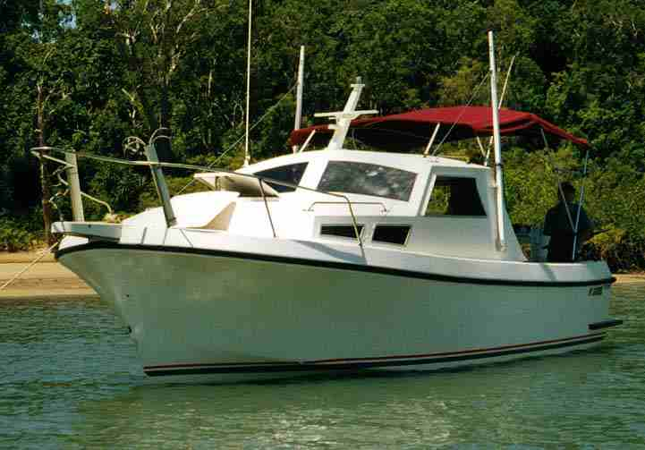 |
LONGBOAT 21 Hi BRUCE, Please find attached a picture of our Roberts Longboat 21 - TARDIS (bitmap format) in Hinchinbrook Channel Far North Queensland. It's a great boat and we go everywhere in her. Power is a Nissan sd22 driving a 16x14 prop through a 2.5:1 reduction box. Max speed is 8 Knots cruise at7.2 knots at 1900rpm which is very economical. In rougher weather we quite often beat tinnies back from the reef (They have white knuckles and we have a beer sitting on the engine box). Thanks for a great design. I have the building bug again. Could you send me the price of 310 boat plans in glass. KIND REGARDS ALLAN BLAIR PO Box 966 Innisfail Qld Australia Ph 0740612128 SEE MORE |
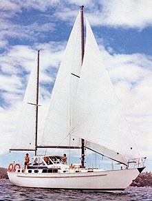 |
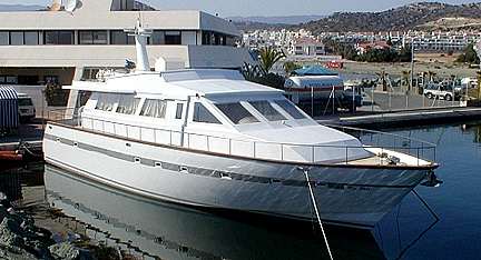
Roberts 43 "Pavanne"
Pilot House Version NEW VERSION Roberts 432 Hi folks, I was looking through your web site as I am considering buying another of your designs which was recently built here in Perth , a current model aft cockpit 43. After looking at many other options, I have come to the conclusion that the 43 ,value for money, safety and performance ,you can't beat it. Its interesting to see that the photo you are using for the pilot house version is an original photo of a boat named "Mellisylou", shown in the early publiCATAMARANion of "Build for Less", built for a guy in Sydney in the mid 70's. I owned the boat for 4 years and sold her in 94,after re-naming her "Pavanne" She has been sold 3 times since and I saw her yesterday at Fremantle Sailing Club. I'm tempted to buy her back . However and more to the point, she's stylish and the design looks as good to-day as it did when it was drawn probably 30 years ago. Good on you Bruce , you're a legend. Kind Regards, Mike Capelle MORE INFORMATION |
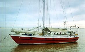 |
Roberts 432
Sailed by Kjell and Berit from their home in Sweden, this Norfolk 43 showed up in the Burnett River to clear for Australia after spending the summer in Australian waters. Their boat plans are to return home via the Suez Canal, alter the accommodation area below, fit some new sails and take off again. Another happy sailing couple fulfilling their dreams |
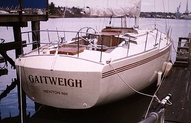 |
Roberts 434 "Gaitweigh" Tony Marcelonis writes: "I was very impressed with you boat plans and office staff as I progressed through building my Roberts 434. As you can see from the photos I used the transom from your New York 46. I have a great boat! The boat was built
using Airex core for the hull and balsa sandwich for the deck. The accommodations fall
line with your New York 46. I can't say enough about your designs. We have three Roberts
designs at the American Yacht Club in Newburyport Ma, a Roberts 28, Roberts 39 and my
Roberts 434. Great boats. I hope you like the pictures."
Signed Tony Marcelonis
|
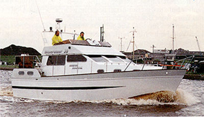 |
Waverunner 38 boat plans and patterns are available to build this boat in FIBERGLASS. The WR38 is available as a planing or semi-displacement powerboat. MORE INFO |